197
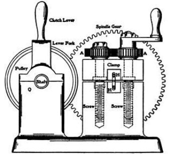
which are four standards for bearings
for two shafts. The pulley, clutch, and
small driving-gear require no
explanation. The wire is clamped
between two jaws H H, [Fig. 1], the
upper one of which is raised or
lowered by the handle and two gears
A A turning right and left screws. The
mandrel or forming-spindle X is of
tool steel finished to fit easily within
the sleeve A, which in turn is fitted
and keyed to turn with the slide, back
and forth within the main spindle V
by a key at D. A handle at Z fastened
to the forming-mandrel by the set-
screw W keeps the mandrel
stationary, by a round-headed pin entering
the back at Y, while the sleeve with the main spindle rotates and twists the wire. This
pin is located in the bracket T, with a spring at the back at S and a handle at R to allow
of its being forced back when the mandrel-lever is to be turned.
When the machine is in use the work is located and clamped between the two jaws H H,
with the pointed end lying in the
slots L and M of the sleeve K and
the spindle V respectively, and
the handle of the forming-
mandrel located and held by the
pin T, [Fig. 1]. The clutch-lever is
then pulled back and the spindle
V and the sleeve K rotate while
the forming-mandrel remains
stationary, thus twisting the wire
around the mandrel to the shape
shown in the half-tone. The
clutch-lever is then pulled out
and the machine is stopped
when Z is released and turned
toward the left, thus drawing out
the sleeve and mandrel, leaving
the finished corkscrew so that it
can be removed by loosening or raising the upper jaw H. The mandrel and sleeve are
then slid back in position, another piece of wire is located, and the operations are
repeated.
Figure 2
Figure 3